
Contents
- Executive Summary: Triangulation in AI Detection
- The Role of Raytracing in Early-Warning Systems
- Method 1: Deterministic Line-of-Sight Triangulation
- Method 2: Probabilistic Volumetric Raytracing
- Implementation Trade-offs: Speed vs. Accuracy
- Sources & References
Executive Summary: Triangulation in AI Detection
Raytracing improves wildfire detection when teams treat smoke pixels as spatial evidence, not as screen artifacts.
The practical decision chain stays short: detect a smoke cue, convert camera pixels into ground coordinates, attach uncertainty, then decide whether field crews need an alert. According to research benchmarks, a useful early-warning design generates a provisional coordinate within 30 seconds to 3 minutes after the first smoke cue. The command center can then refine confidence within 3 minutes to 15 minutes when weather, terrain, and multi-frame observations arrive. That split matters because dispatch does not wait for perfect geometry.
Key takeaways for model selection
- Deterministic line-of-sight triangulation fits first-alert workflows where at least two optical sensors share surveyed positions, known camera intrinsics, synchronized timestamps, and a common coordinate framework.
- Probabilistic volumetric raytracing fits verification workflows where smoke drift, terrain occlusion, camera covariance, and wind fields affect the ignition estimate.
- Coordinate exchange needs discipline. WGS 84 works for exchange, but a local projected grid should handle distance calculations and operational map products.
- Forestry teams should select by dispatch role. Edge nodes should favor deterministic speed; command centers should run volumetric verification when the added computation can still influence the active incident.
Bottom Line: Treat triangulation as a staged detection system: fast geometry at the camera, uncertainty modeling at the command center.
The Role of Raytracing in Early-Warning Systems
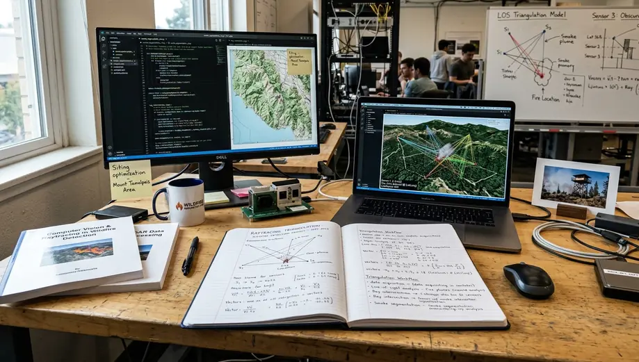
Raytracing maps optical sensor observations onto a 3D terrain model. The workflow begins with camera calibration, solves exterior orientation against surveyed control points, and casts a ray from the camera center through the smoke pixel into the terrain scene. That ray can hit a digital elevation model, pass above a ridge, or intersect with a ray from another camera. The system then converts a visual cue into a coordinate that a dispatcher can compare with roads, lookouts, fuel breaks, and administrative boundaries.
From 2D intersections to terrain-aware vectors
Basic 2D intersection assumes a flat map. It often looks convincing until the camera network covers steep ridges, drainage cuts, or hidden ignition bases. A deterministic intersection on a map plane can place a plume on the visible slope while the actual ignition sits behind the ridge. That failure case is common enough that field teams should design against it before the first smoke season.
Terrain-aware 3D vectoring adds elevation to the coordinate chain. The concrete layers are not exotic: camera pose in a projected coordinate system, DEM tiles at 1 m to 30 m ground sampling distance depending on source, a canopy or surface model where available, and GIS layers for fire roads, lookouts, and management boundaries.
GIS integration and refresh cadence
Forestry GIS databases give raytracing its operational context. A point without access routes, slope position, and jurisdictional boundaries slows dispatch. A coordinate tied to the wrong elevation band can send crews toward a dead-end road.
Managed forests should review LiDAR-derived elevation baselines, as noted in industry reports, every 12 to 36 months. Satellite or aerial surface updates deserve review every 7 to 30 days after logging, windthrow, landslide, or recent burn activity. The implication is simple: raytracing quality depends as much on terrain freshness as on camera resolution.
Method 1: Deterministic Line-of-Sight Triangulation
Deterministic triangulation calculates direct vector intersections from dual-camera setups. It is the right first method when the system must run on low-power equipment and produce a provisional coordinate quickly.
Step-by-step mechanics
- Isolate the smoke region in each camera frame.
- Select a centroid, leading-edge pixel, or another stable plume feature.
- Undistort the pixel using known lens distortion parameters.
- Convert the corrected pixel into a bearing vector using camera intrinsics.
- Transform the bearing into the common projected coordinate system using azimuth, tilt, and surveyed camera position.
- Intersect the vector with a second camera ray, terrain surface, or both.
The minimum operating detail is strict: two camera stations with surveyed coordinates, known lens distortion parameters, azimuth and tilt calibration, and timestamp alignment tight enough that both cameras compare the same plume feature across frames.
Why it works at the edge
Single-frame geometric triangulation can run at the camera cadence or scan cadence. In typical edge deployment planning, the local processing interval ranges from 1 second to 60 seconds depending on image resolution, candidate pixel count, and whether the same device also runs smoke classification. That makes deterministic geometry useful for solar-powered stations that cannot spend every thermal cycle on dense 3D inference.
Field Note: The best deterministic deployments treat calibration as a maintenance task, not as a commissioning artifact. A slight tilt shift after wind loading can move the projected ray farther than a dispatcher expects.
Known vulnerabilities
Heavy smoke, thermal inversion layers, and ridge-line occlusion can distort the relationship between the visible plume and the ignition base. A specific failure case: two ridge-top cameras may intersect on the wrong slope when a smoke column rises behind a ridge and the base is hidden. The coordinate can look plausible, yet place the crew downwind of the true source or on terrain that vehicles cannot reach.
That does not make deterministic triangulation weak. It defines its job. Use it to start the clock, not to end the investigation.
Method 2: Probabilistic Volumetric Raytracing
Probabilistic volumetric raytracing starts with the same camera rays but refuses to collapse them into one coordinate too early. It builds a 3D volume over the terrain and assigns uncertainty to camera calibration, segmentation masks, wind movement, plume shape, and atmospheric refraction.
Probability cloud construction

The model samples many plausible ray paths through the terrain volume. Monte Carlo simulations then generate a probability cloud for the ignition source rather than a single intersection point. Each sample can account for plume drift, changing wind direction, and partial occlusion. The result gives dispatchers a ranked search area instead of an overconfident point.
This method suits mixed-elevation valleys where morning inversion, canopy gaps, and drifting smoke can move the visible plume away from the source. A dry conifer stand with clear sight lines may not need that extra machinery for the first alert. A valley with layered air and broken canopy often does.
Required mesh inputs
- DEM or surface model for terrain constraints.
- Recent optical or thermal imagery for canopy and fuel-break geometry.
- Wind observations or short-term wind fields.
- Camera calibration covariance.
- Smoke segmentation mask.
- Time-indexed plume observations from multiple frames.
High-fidelity satellite or aerial imagery matters because the volumetric mesh needs current surface structure. Imagery acquired within 7 to 30 days is useful for rapidly changing canopy or post-disturbance terrain. Older 3 to 12 month imagery may be acceptable in stable forest blocks if roads, clearings, and canopy height have not materially changed.
Edge cases that change the answer
Probabilistic models can absorb uncertainty, but they cannot invent missing operational inputs. If the command center lacks recent terrain imagery, weather fields, or multi-camera observations, the probability cloud may arrive too late to change dispatch. In that case, the method becomes post-incident analysis rather than early warning.
Implementation Trade-offs: Speed vs. Accuracy
The implementation decision is staged rather than binary. Edge nodes run deterministic triangulation to keep the first alert fast and bandwidth-light. The command center then runs volumetric raytracing for secondary verification when richer context is available.
Operational selection matrix
| Decision factor | Deterministic line-of-sight triangulation | Probabilistic volumetric raytracing | Recommended operational use |
|---|---|---|---|
| Primary output | Single provisional coordinate or narrow intersection zone. | Probability cloud over terrain and canopy volume. | Use deterministic output for initial alerting; use volumetric output for confidence refinement. |
| Latency role | 30 seconds to 3 minutes after a smoke cue in the edge stage. | 3 minutes to 15 minutes when terrain meshes, wind fields, and plume motion are added. | Keep first dispatch decisions fast, then update priority as verification improves. |
| Hardware fit | Well suited to low-power camera nodes and constrained uplinks. | Better suited to command-center compute with access to imagery and weather feeds. | Do not force dense volumetric processing onto every remote tower. |
| Main risk | Wrong-slope intersections under occlusion, smoke distortion, or inversion layers. | Late verification if data ingestion and compute queues lag the incident timeline. | Design escalation rules before fire season, not during the event. |
Solar-powered IP67 edge nodes
IP67 enclosures are dust-tight and rated for temporary immersion up to 1 m for 30 minutes under IEC 60529. That rating says nothing about sustained GPU heat rejection in direct sun. An edge node can remain sealed against dust and brief water immersion yet still throttle under solar gain if the enclosure lacks a validated heat path from processor to housing.
This is the trade-off that bites field deployments: sealing improves environmental survivability, while dense compute raises thermal load inside the sealed box. The workaround is not to weaken the enclosure. Run deterministic triangulation locally, transmit compact coordinate and mask metadata, and reserve volumetric computation for the command center.
Important: Volumetric verification is practical only when the command center can ingest recent terrain imagery, weather fields, and multi-camera observations fast enough to influence the active dispatch decision.
Sources & References
The reference set should be selected by function: ray geometry for intersection math, geospatial standards for DEM and metadata handling, wildfire geospatial guidance for coordinate reporting, and hardware documentation for environmental constraints. Algorithmic foundations remain relevant when implementations still use them; operational and hardware guidance should stay current for the deployment window.
Academic Sources
- Ray-triangle intersection methods such as Moller-Trumbore geometry remain useful anchors for terrain surface intersection.
- Voxel traversal methods such as Amanatides-Woo style grid stepping support volumetric mesh traversal.
- GeoTIFF and ISO geospatial metadata practices support DEM exchange, coordinate traceability, and map product consistency.
- Primary research on topographical mapping algorithms should be reviewed alongside operational GIS requirements.
- Official forestry standards for optical detection help define coordinate reporting expectations and detection-system acceptance criteria.
For Fireball IT deployments, the recommendation is firm: deploy deterministic line-of-sight triangulation on every camera node for the first coordinate, then run probabilistic volumetric raytracing at the command center before escalating crew priority in complex terrain.






Discussion
No comments yet.