
Executive Summary: Core Mapping Protocols
The workflow begins by classifying each incoming image as a rapid-response layer or a measurement-grade layer. Analysts first attach a coordinate reference system and inspect embedded metadata to determine the appropriate processing path. Coordinate systems must be declared explicitly. We assign WGS 84 geographic coordinates for multi-agency interchange or the relevant UTM zone for metric fireline measurements.
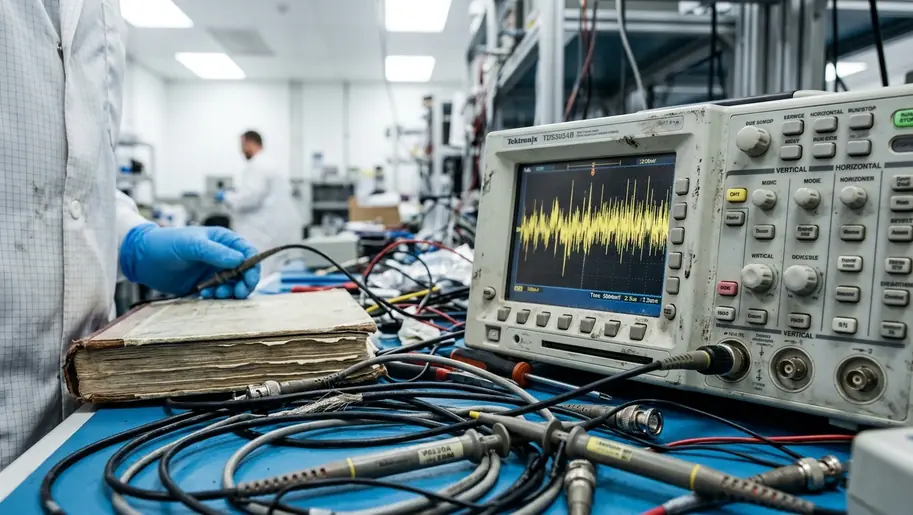
Basic georeferencing relies on translation, rotation, scaling, and affine or polynomial transformation. Orthorectification demands a heavier computational lift, using sensor geometry, acquisition angle, and a digital elevation model to correct optical distortion. For active incident mapping, an initial georeferenced product can be prepared in a 15- to 45-minute window after receipt of a usable airborne frame set. A terrain-corrected release commonly requires a 45- to 150-minute processing window depending on DEM availability and scene size.
Bottom Line: A complete mapping protocol delivers three specific outputs: a coordinate-tagged image, a terrain-corrected image, and a validation report detailing residual error values from independent check points.The Foundational Protocol: Georeferencing Wildfire Data
Analysts first inspect the image header for acquisition time, approximate sensor position, focal metadata, and any existing spatial tags. They then select ground control points from features that remain static during the incident. Reliable GCP candidates include bridge abutments, paved road intersections, culvert mouths, runway corners, dam structures, utility substations, and survey monuments visible in reference layers.
Unstable or ambiguous GCPs ruin coordinate geometry. We exclude flame fronts, smoke edges, dozer lines, vehicle locations, river edges after suppression withdrawals, fresh ash boundaries, and canopy gaps.
Control points should be distributed near the image corners and center, not clustered around the fire perimeter. Clustered points can make the perimeter appear accurate while the rest of the image warps. Minimum control geometry requires at least 4 well-distributed GCPs for an affine transform, though 6 to 12 GCPs are preferable for polynomial correction across a full aerial frame. In a smoke-obscured operational scene, GCP selection and first-pass transformation should be budgeted for 10 to 30 minutes per image strip when reference basemaps are already cached.
Important: A thermal frame that aligns cleanly to road intersections on a valley floor can still misplace a ridge-top fire edge if it was georeferenced but not orthorectified.Advanced Terrain Correction: The Orthorectification Process
The orthorectification step starts after analysts decide that terrain displacement matters for the incident objective, such as mapping a fire edge crossing a canyon or validating structure exposure on a slope. Variables controlled during orthorectification include sensor position, pitch, roll, yaw, focal length, principal point offset, terrain elevation, earth curvature, and map projection.
DEM selection dictates the correction quality and should be recorded with cell size and source date. Common operational inputs include roughly 10-meter national elevation grids, 30-meter regional grids, or sub-meter to 2-meter lidar-derived DEMs where local data exists. While orthorectification significantly reduces terrain displacement, absolute pixel accuracy remains constrained by the spatial resolution of the underlying elevation model.
Processing algorithms differ by hardware. For pushbroom satellite imagery, rational polynomial coefficients or a physical sensor model are used. For frame-camera aerial imagery, collinearity equations and calibrated interior orientation parameters drive the correction. During the final phase, nearest-neighbor resampling preserves original digital numbers for binary or categorical fire masks. Bilinear interpolation modifies pixel values and should be flagged when thermal intensity is later compared across scenes.
A 10- to 25-square-kilometer airborne fire scene can often be orthorectified in a 20- to 90-minute processing window when DEM and trajectory files are already local. Pulling a missing DEM from an external archive can add 30 to 120 minutes.
Capturing Attitude and Vector Parameters
During acquisition, the mapping crew records the aircraft or platform trajectory and camera exposure timing as a single synchronized observation stream. The processing decision is made at import: if the trajectory data is missing or corrupt, the analyst must revert to manual georeferencing.
Essential per-exposure metadata fields include UTC acquisition time, latitude, longitude, ellipsoidal height, pitch, roll, yaw, sensor identifier, focal length, exposure duration, and frame number. In standardized test environments, IMU logging rates used in aerial mapping commonly fall in the 100- to 400-Hz range, while GNSS trajectory logs are often captured at 1 to 20 Hz and interpolated to exposure time. A pulse-per-second or equivalent hardware trigger should tie camera exposure to GNSS time. The timestamp audit should document whether exposure records are aligned within a 1- to 10-microsecond logging resolution or only to millisecond precision.
A high-resolution sensor does not guarantee high coordinate accuracy when exposure timing, IMU attitude, or camera-to-GNSS lever-arm offsets are missing.
Boresight calibration should be repeated after sensor remounting, hard landing, gimbal replacement, or a documented change in camera bracket geometry. A practical pre-incident calibration flight can be completed in a 35- to 90-minute window using opposing flight lines and cross-strips over roads, rooftops, and other high-contrast static features.
Equipment Calibration and Sensor Integration
Calibration is handled before acquisition, during acquisition, and again during processing. Before flight, operators warm the sensors, verify focus, check shutter timing, and confirm that the lens model matches the processing software profile. Pre-flight checks should include lens focus lock, aperture setting, exposure mode, thermal gain range, shutter or non-uniformity correction status, GNSS lock, IMU status, and storage write verification.
Thermal sensors should complete manufacturer-specified warm-up before calibration capture. An operational warm-up window of 10 to 30 minutes is typical for field planning. A complete pre-flight sensor and timing check for an airborne wildfire mapping sortie should be scheduled for 25 to 60 minutes before launch, with an additional 5- to 15-minute recheck after payload power cycling.
Lens calibration records should include focal length, principal point, radial distortion coefficients, tangential distortion coefficients, sensor pixel pitch, and calibration date. Radiometric thermal calibration should use blackbody or equivalent reference targets when measurement-grade temperature interpretation is required. Tactical perimeter mapping can instead document relative thermal thresholds and avoid claiming absolute temperature.
Addressing Topographical Anomalies in Active Fire Zones
When terrain or atmosphere distorts the scene, analysts first separate geometric error from visibility error. Geometric error is handled through a better DEM, improved trajectory data, or stricter orthorectification parameters. Heat plumes can create local image shimmer and apparent edge displacement. Analysts should flag pixels along active flame columns rather than treating them as stable control features.
Steep canyons require GCPs on both sides of the drainage, not only along the valley road, because a valley-only control network can hide ridge displacement. Smoke-shadow combinations should be masked as a separate uncertainty class when they obscure the terrain surface but not the thermal anomaly.
Field Note: A DEM that was accurate before a debris flow, road reconstruction, or high-severity burn scar can introduce systematic terrain correction error after the landscape changes.DEM currency checks should compare the elevation source date against known recent disturbances, including landslide mapping, flood scouring, road reconstruction, and high-severity burn scars. For an active incident, a DEM anomaly review can be completed in 10 to 30 minutes using cached terrain layers. Building a revised terrain surface from new stereo imagery or lidar is a 2- to 12-hour task when source data is already available.
Quality Assurance and Coordinate Accuracy Validation
Quality assurance begins only after control points used for fitting are separated from check points used for validation. Independent check points should not be reused as GCPs. Suitable checks include surveyed road intersections, bridge corners, building corners, utility pads, and permanent runway markings.
The analyst calculates residuals at independent check points and inspects spatial alignment against static infrastructure. Cross-reference layers should be static and independently sourced, such as cadastral control, local government road centerlines, surveyed hydrants, transmission structures, and permanent facility footprints.
QA output should include horizontal RMSE, maximum observed residual, number of GCPs, number of check points, coordinate reference system, DEM source, resampling method, and analyst release time. A rapid QA pass for emergency release should be budgeted for 10 to 25 minutes per scene. A measurement-grade QA package with documented residual plots and metadata review commonly takes 1 to 4 hours.
Final delivery to emergency coordinators should include the image, perimeter or hotspot vector layer, uncertainty mask, metadata file, and a short readme identifying whether the product is georeferenced or orthorectified. Stop delivering unrectified thermal overlays to ground crews. Mandate that every rapid-response map includes a documented coordinate reference system and a quantified residual error report, ensuring incident commanders base their evacuation lines on verified geometry rather than optical illusions.
Academic Sources
- GeoTIFF 1.1 standard for embedded raster georeferencing tags and coordinate metadata.
- ISO 19111:2019 for coordinate reference system definitions and coordinate operations.
- ISO 19115-1:2014 with later amendments for geospatial metadata structure, including lineage and quality fields.
- Current edition of digital geospatial positional accuracy standards from the relevant professional geospatial body when reporting RMSE and checkpoint validation.
- National Geospatial Program specifications for DEM resolution, vertical datum, and lidar-derived terrain products.
- Remote Sensing of Environment for primary research on thermal sensor calibration and atmospheric refraction modeling.




Discussion
No comments yet.