
Executive Summary: The Camera Placement Protocol
The placement protocol starts by separating terrain suitability from installation feasibility. Analysts first model what a camera could theoretically see, then progressively subtract canopy blockage, atmospheric interference, and local hardware constraints. A defensible workflow runs in five ordered phases: elevation and LiDAR acquisition, algorithmic viewshed modeling, environmental-variable adjustment, drone and ground verification, and final hardware calibration.
For recent regional deployments, a practical planning window is 40-85 calendar days from data inventory to final baseline viewshed documentation, assuming LiDAR coverage already exists. We control specific variables throughout this window. These include observer elevation, target height, terrain line of sight, Digital Surface Model (DSM) canopy height, solar azimuth and elevation during low-angle light periods, and mast clearance above immediate foreground obstructions.
Executing this protocol requires a strict toolchain. Teams need GIS software capable of raster viewshed analysis, recent DEM or LiDAR-derived bare-earth data, DSM or canopy-height rasters, a GPS-enabled drone for verification, and a georeferenced field-photo archive.
Phase 1: Digital Elevation Modeling and Data Acquisition
The team first fixes the study boundary, then builds a baseline terrain model before any camera coordinates are proposed. Candidate ridgelines, existing towers, and accessible high points are inventoried against available topographic datasets.
For initial regional screening, 10-meter elevation rasters can identify broad ridgelines. Final camera placement requires 1-meter bare-earth DEMs where LiDAR coverage is available. According to research benchmarks, Quality Level 2 datasets are commonly specified with aggregate nominal pulse spacing near 0.7 meters and vertical RMSEz not exceeding about 10 centimeters in open terrain.
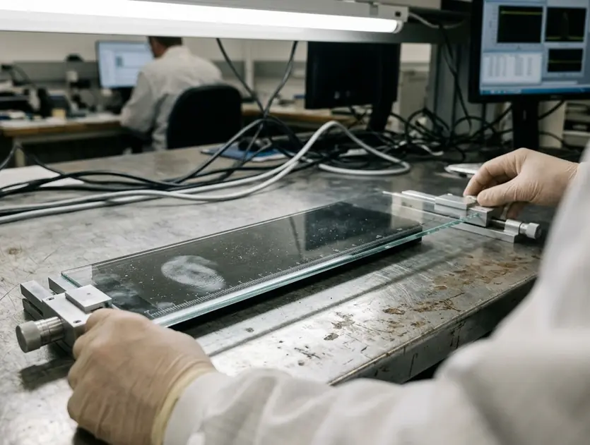
Data currency dictates the accuracy of obstruction models. Analysts must log the acquisition season of the source data. Leaf-on LiDAR captured from May to October and leaf-off LiDAR captured from November to March produce materially different obstruction assumptions in mixed conifer-hardwood terrain.
Field Note: The theoretical detection radius should be stored as an explicit model input derived from camera focal length, sensor resolution, required smoke-plume pixel footprint, and agency alerting distance. It should never be inferred from terrain alone.
Phase 2: Algorithmic Viewshed Analysis
Analysts run a first-pass viewshed from each candidate high point using bare-earth elevation, then rerun it with DSM or canopy-height layers to remove terrain cells blocked by trees and built structures. For recent deployments using existing LiDAR, a normal viewshed iteration cycle spans 5-15 working days for a single planning unit after all elevation, canopy, and candidate-site layers are in hand.
Observer height must equal the proposed mast height plus the camera optical-center height, recorded in meters above ground level at each candidate coordinate. Target height should be tested as a parameter rather than fixed universally. Smoke-column onset, treetop-level smoke, and horizon-level plume detection produce materially different visible-area outputs.
Line-of-sight rasters should be generated at the same cell size as the final DEM or resampled explicitly. The resampling method must be documented to avoid mixing 1-meter local terrain with 10-meter regional grids without traceability.
A DSM-based viewshed reflects mapped canopy and structures at the exact time of the LiDAR or photogrammetry survey; fast post-survey vegetation growth, salvage logging, or new tower construction can invalidate local obstruction assumptions before installation. This temporal decay in data accuracy requires strict field validation.
Phase 3: Environmental Variable Integration
Once topographic visibility is known, the model is adjusted for optical reliability. Solar geometry is mapped against each camera azimuth, seasonal haze records are reviewed, and thermal-distortion risks are calculated.
Solar glare screening calculates sun azimuth and elevation sampled at around 5-15 minute intervals during sunrise and sunset windows for the main fire season months defined by the agency. High-risk glare periods are flagged when the sun path aligns with planned PTZ sweep bearings at low solar elevation. This is especially critical for east-facing morning surveillance and west-facing evening surveillance.
Atmospheric inputs rely on station-based visibility observations, fire-weather station records, and seasonal smoke or haze logs from recent fire seasons where available. A site that performs well in a dry, high-elevation basin may underperform in a coastal or valley setting where morning marine haze, inversion layers, or low sun angles repeatedly reduce usable optical range.
Thermal distortion requires specific attention on long sightlines. It is most relevant when sightlines cross heated rock, open chaparral, dry grassland, paved corridors, or basin floors during afternoon heating periods.
Phase 4: Field Verification Protocol
Field verification turns the GIS shortlist into installation-grade evidence. Crews send a drone to the proposed coordinate and mast-equivalent height, capture a full horizon panorama, and compare visible landmarks against the simulated viewshed.
Drone verification must be flown at the proposed optical-center height above ground level, not merely above the ridge surface. This ensures the captured panorama matches the modeled observer height. A 360-degree image set should include overlapping frames or a stitched panorama, compass orientation, GPS coordinate, flight altitude above launch point, and timestamp.
Ground crews document micro-obstructions within the near field. Rock outcrops, individual trees, antenna rails, utility poles, and local ridgeline breaks often fail to appear in satellite imagery but will block a camera lens.
Important: For shortlisted sites, schedule field verification within 20-45 calendar days after GIS ranking so seasonal vegetation and access conditions still correspond to the modeled assumptions.
Phase 5: Hardware Calibration and Final Positioning
Final placement is determined by reconciling the verified panorama with hardware constraints. Mast height is raised only enough to clear immediate obstructions, and PTZ sweep patterns are assigned to the most critical detection zones.
Mast-height testing compares candidate heights in fixed increments, such as 3 meters, where engineering and permitting allow. Small height changes can clear foreground trees without materially changing distant terrain occlusion. A ridge camera with a long theoretical optical radius can still fail to detect smoke in a narrow canyon if a secondary ridge blocks the first 2-5 kilometers of the sightline from the camera position.
The final baseline package must include the installation coordinate, mast height, optical-center height, true-north reference, PTZ preset list, panoramic verification imagery, and the final accepted viewshed raster.
Verification data supports completing post-installation calibration during a clear-weather window of 5-10 days. This ensures lens focus, horizon alignment, and PTZ repeatability are validated under stable visibility conditions.
Academic Sources
References are selected for operational repeatability. Elevation-data standards establish measurable terrain inputs, and fire-lookout viewshed literature supplies the placement logic for line-of-sight analysis.
- United States Geological Survey (USGS). 3D Elevation Program (3DEP) Standards. This documentation provides the relevant LiDAR quality-level terminology, vertical accuracy expectations, and DEM production context used for terrain modeling.
- USDA Forest Service. Methodologies in Viewshed Analysis for Fire Lookout Placement. These methodologies provide the applied basis for using terrain visibility, access, and obstruction review in fire-detection siting.
Operational records should preserve dataset title, source agency, acquisition date range, horizontal coordinate system, vertical datum, raster cell size, and processing date for every DEM, DSM, and canopy layer used. For recent audits, retaining the full GIS processing log and field-verification archive for at least one complete fire season after installation gives agencies a defensible baseline for performance review.
Bottom Line: Lock your PTZ sweep parameters exclusively to high-risk ignition corridors, settlement interfaces, and lightning-prone ridges. Abandon the default practice of dividing the horizon into even compass bearings; direct your sensor time entirely toward the vectors where early detection dictates containment success.




Discussion
No comments yet.